Interrupts: IM1, IM2, and the Next’s Multi-Source Interrupt System
So far in this book the CPU has been firmly in charge. It executes one instruction, then the next, and decides for itself when to read a port or rewrite an MMU register. From this chapter onward, that picture changes. The ULA wants to tell you a frame finished. A CTC channel wants to tell you a microsecond budget elapsed. A UART has a byte ready. The DMA controller has finished a transfer. Each of these is an interrupt — a hardware signal that yanks the CPU away from whatever it was doing and runs your handler instead.
This chapter pays the conceptual cost once, so every later chapter — CTC, line-interrupt palette tricks, DMA completion, UART receive, even the Copper — can lean on the same vocabulary. We’ll cover the three Z80 interrupt modes, the role of the I and R registers introduced in Z80N: The Next’s Z80 CPU, and the Next’s hardware-driven IM2 controller that turns the classic vector table into a deterministic, multi-source dispatch system.
Once you understand the dispatch model, the same machinery serves every interrupt source on the machine.
What an Interrupt Actually Is
An interrupt is a signal on a wire. On the Z80 there are exactly two such wires: /INT (maskable) and /NMI (non-maskable). When /INT goes low and the CPU’s internal IFF1 flag (Interrupt Flip-Flop 1) is set, the CPU finishes its current instruction, then — instead of fetching the next one — performs a special acknowledge cycle and jumps to a handler (an ISR, or Interrupt Service Routine). When /NMI goes low, the CPU jumps to a handler regardless of any flag.
That’s the whole mechanical story. Everything else — vector tables, priority chains, status flags, the Next’s hardware IM2 controller — is software and FPGA logic built on top of those two wires.
When signals are sampled
The Z80 checks /INT at the end of every instruction — specifically during the last T-state before the M1 (opcode fetch) of the next instruction. If /INT is low at that exact moment and IFF1 is set, the CPU responds instead of fetching. If the signal arrived but went away before that sample point, the interrupt is missed entirely.
/NMI is edge-triggered, not level-sensitive. The Z80 latches the falling edge internally; once the latch is set the NMI will be serviced even if the signal returns high before the current instruction finishes. A sustained low on /NMI does not re-trigger a second NMI — only a new high-to-low transition does.
/INT is level-sensitive — and that has consequences
Unlike /NMI, /INT is level-sensitive. The CPU doesn’t latch a pulse; it only asks “is the wire low right now?” at the sample point. This has two important consequences:
- The signal must still be low at the sample point. A very short pulse (shorter than one instruction) can go unnoticed. Hardware designers therefore keep
/INTasserted until the CPU acknowledges. - If the signal stays low after the handler finishes, the interrupt fires again immediately. As soon as
EIre-enables interrupts, the CPU samples/INT, finds it still low, and dives back into the ISR — over and over, until the stack overflows. This is why clearing the interrupt source before executingEIis not a style preference; it is a hard requirement.
On the Next, the exact latch depends on the interrupt mode. In legacy pulse mode, the readable pending bits in NextReg $C8/$C9/$CA are the things you clear by writing 1s. In hardware IM2 mode, each source also has a daisy-chain request/in-service state: acknowledge moves the winning source into service, and RETI releases it. Clearing the readable status bit is still useful, but RETI is what tells the hardware IM2 chain that the current ISR has finished.
The two flags that govern maskable interrupts are:
- IFF1 — the “interrupts enabled” flag.
EIsets it;DIclears it. WhenIFF1 = 0,/INTis ignored. - IFF2 — a backup copy of IFF1 that NMI uses to remember the pre-NMI state.
After EI, interrupts are not actually enabled until one more instruction has executed. This protects the standard interrupt epilogue: EI; RETI for maskable interrupts, or EI; RETN when an NMI handler deliberately restores the previous interrupt state. The return instruction runs before the next maskable interrupt can fire, so you don’t recursively re-enter the handler before unwinding the stack. We’ll come back to why RETI and RETN matter later in this chapter.
The Three Z80 Interrupt Modes
When /INT fires and IFF1 is set, the CPU’s response depends on which of three modes it’s in. The mode is selected by the IM 0, IM 1, or IM 2 instructions and remembered until you change it.
IM 0 — the legacy CP/M mode
In IM0, the interrupting device puts an instruction byte on the data bus and the CPU executes it. In practice that instruction is almost always RST n (a single-byte call to one of $00, $08, $10, …, $38). This was used on early CP/M systems where multiple peripherals each had a dedicated RST vector.
On the Spectrum and the Next, IM0 is not used by any system software. We mention it here so you know what IM 0 does if you stumble across it — and so you can understand what would happen if you accidentally engaged it on the Next.
IM 0 on the Next: what actually happens
If you execute IM 0 in your program, the Next’s ULA still fires the 50 Hz /INT pulse as usual. The Z80 enters its interrupt acknowledge cycle and reads a byte from the data bus — but no device on the Next is wired to place a valid instruction byte there during an IORQ/M1 acknowledge cycle. The bus floats, and the pull-up resistors hold it high. The CPU therefore reads $FF.
$FF is the opcode for RST $38 — the same address IM1 would call. So in practice, on the ZX Spectrum Next, IM0 accidentally behaves almost identically to IM1: every interrupt calls $0038.
The “almost” is the problem. A floating bus is not guaranteed to read $FF. On a real board with an expansion device plugged into the edge connector that actively drives the bus, or simply due to bus capacitance effects and timing, you could read something else entirely. $76 (HALT), $F3 (DI), or any other single-byte opcode could execute in the context of the CPU’s acknowledge cycle — with consequences that range from weird to catastrophic. The CPU state at that moment (stack pointer, register values) is whatever the interrupted code left behind, so even a HALT lands you in a frozen machine with no obvious reason.
The takeaway. IM0 is not a danger you’ll accidentally trigger —
IM 0is a deliberate instruction — but it is a mode you should never use on the Next unless you have hardware on the expansion bus that explicitly drives valid opcodes during the acknowledge cycle. If you find yourself in IM0 unexpectedly (perhaps after returning from a routine that forgot to restore the mode), the symptom is usually random crashes or a machine that appears to be in IM1 but behaves erratically under load.
IM 1 — the Spectrum default
In IM1, the CPU ignores the data bus and unconditionally calls $0038. That’s it. One vector, one handler, hard-coded into the silicon.
This is the mode the original Spectrum 48K ROM uses. The handler at $0038 services the 50 Hz ULA frame interrupt: it scans the keyboard, increments the system frame counter at FRAMES ($5C78), and returns. Any code that runs under the ROM’s interrupt model is using IM1.
On the Next, the firmware’s regular interrupt path has more plates spinning than the old 48K ROM. NextZXOS still has to keep the classic heartbeat alive, but it may also run operating-system housekeeping and installed driver work: keyboard/editor state, mouse or joystick integration, DivMMC/NextZXOS service hooks, UART/ESP-related work, and other firmware callbacks depending on the machine state. The practical lesson is simple: if you replace the firmware’s IM1 handler, you are not just stealing a frame counter. You may be cutting the butler’s bell wire while dinner is still being served.
For new Next code, IM1 is fine when you only need one interrupt source — typically the ULA frame interrupt for a “do something every 1/50 second” pattern. It’s the smallest commitment: no vector table, no LD I,A, no NextReg setup. The catch is that $0038 lives in slot 0 (ROM), so to install your own IM1 handler you’d need to swap in a RAM page there or hook through NextZXOS’s API — either of which is more work than just switching to IM2.
IM 2 — the vectored mode
This is where the Next gets interesting. In IM2, when /INT fires:
- The interrupting device (or, on the Next, the FPGA’s interrupt controller) places an 8-bit vector byte on the data bus.
- The CPU forms a 16-bit address by combining the
Iregister (high byte) and that vector byte (low byte). - It reads two bytes from that address — a little-endian 16-bit handler pointer.
- It pushes the current PC onto the stack and jumps to the handler.
So IM2 dispatches through a table of pointers in memory, indexed by which device fired. Different sources can land in different ISRs without any test or branch in your code.
The vector byte is the low byte of the table lookup. In a tidy Z80 system, interrupting peripherals normally supply even vectors, because each table entry is a two-byte pointer and you do not want neighbouring entries to overlap like badly parked cars. On the Spectrum and the Next, the important rule is more practical: know who is driving that vector byte. If nothing deterministic is driving it, treat all 256 possible values as suspect.
The I and R Registers
Two single-byte registers come along with IM2:
I— the Interrupt Vector register. Its content forms the high byte of the IM2 dispatch address. You set it withLD I,A.R— the Memory Refresh register. It’s auto-incremented after every M1 (instruction-fetch) cycle to drive DRAM refresh. You can read and write it (LD A,R/LD R,A), but its primary use is as a low-quality random-number source. The interrupt logic doesn’t useRat all.
Two quirks of R are worth knowing:
-
Bit 7 is never touched by the auto-increment. The CPU increments only bits 6:0; bit 7 is preserved exactly as you wrote it with
LD R,A. If you set bit 7 with aLD R,Awrite, it stays set through every subsequent increment. This was by design — the original DRAM refresh circuitry used bit 7 as a bank-select that the refresh counter shouldn’t disturb. -
LD A,Rcopies IFF2 into the P/V flag. When you executeLD A,R, the CPU loadsAwith the current value ofRand sets the flags as follows: S reflects bit 7 of the result, Z is set if the result is zero, H and N are cleared, and — the important one — P/V is set to the current value of IFF2 (the backup copy of the interrupt-enabled flag).LD A,Ihas the same side-effect. This is the standard way for an NMI handler to find out whether interrupts were enabled in the code it interrupted: afterLD A,R(orLD A,I), test the P/V flag withjp pe(P/V = 1 → interrupts were on) orjp po(P/V = 0 → interrupts were off).
Programs almost never touch R deliberately. They almost always touch I, and the standard sequence to enable IM2 looks like this:
    di                  ; Disable interrupts while we set things up
    ld a,$80            ; Vector table is at $80xx
    ld i,a
    im 2
    ei
After this, every time /INT fires the CPU forms an address $80vv (where vv is the vector byte) and dispatches through the two-byte pointer stored there.
Why a register, not a fixed address? Decoupling the table location from the CPU lets a program place its vector table wherever it has free memory. Different programs can use different
Ivalues without conflict; even cooperating programs can swap tables in and out by changingIand a singleEI.
The Classic IM2 Trick: the All-$FF Table
Here’s the puzzle. In IM2, the Z80 uses the byte on the data bus as the low byte of the table address. Classic Z80 peripherals are expected to provide sane, even vector values, but the original Spectrum has no interrupting peripheral politely handing over a clean vector. In practice the floating bus is commonly read as $FF; on expanded machines, some other hardware can accidentally leave a different value on the bus. The bus byte is not a butler with a tray. It is more like a note shoved under the door in the dark.
The classic safe IM2 setup goes like this:
- Fill 257 consecutive bytes with the same byte value, say
$81— that is, addresses(I << 8) + $00through(I << 8) + $100. - Place your real ISR at address
$8181(low byte = high byte =$81).
When the interrupt fires, no matter what byte the data bus delivers, the CPU forms a table address somewhere from (I << 8) + $00 to (I << 8) + $FF. It reads two bytes starting there. Because every possible adjacent pair contains $81,$81, the fetched pointer is always $8181.
The awkward extra byte is there for the $FF case. If the vector byte is $FF, the CPU reads the low byte at (I << 8) + $FF and the high byte at (I << 8) + $100, just over the page boundary. That makes 257 bytes the fully defensive table size.
This also explains why the table is filled with the same value in every slot. If your interrupt source guarantees even vector bytes, you can use a normal table of two-byte entries: offset $00/$01 for one handler pointer, $02/$03 for another, and so on. You do not need the odd and even bytes to be identical in that case. The repeated-byte trick is for the untidy “who knows what the bus will say?” case.
Hence the name “all-$FF table” — although the phrase is a little muddy. The unpredictable Spectrum bus often supplies $FF, but the bytes you fill into RAM are usually $81 (for handler $8181), $80 (for handler $8080), or whatever repeated byte points at a convenient safe address.
This trick gives you a single ISR for all IM2 interrupts — perfect when there’s only one source, less useful when you actually want different handlers for different devices. The Next’s hardware IM2 mode (covered next) sidesteps the trick entirely by guaranteeing the vector byte.
The Next’s Hardware IM2 Mode
The Next’s FPGA includes an interrupt controller that, when enabled, drives the IM2 vector byte deterministically from a fixed priority table. No bus floating, no all-$FF workaround, and one ISR per source.
You enable it via NextReg $C0 bit 0:
    nextreg $c0,%01100001     ; bits 7:5 = $60 = im2 vector top bits
                              ; bit 0    = 1 → enable hardware IM2 mode
With hardware IM2 mode on, the FPGA forms the vector byte as:
vector = (NR_C0[7:5] << 5) | (priority << 1)where priority is a fixed 4-bit number assigned to each interrupt source in the FPGA. The result is a vector byte where:
- Bits 7:5 are the three programmable top bits from NR
$C0. They place the table somewhere in the page (eight 32-byte windows:$00,$20,$40, …,$E0). - Bits 4:1 are the source priority (0–13).
- Bit 0 is always 0 — every entry is a 16-bit pointer on a 2-byte boundary.
So with I = $80 and NR $C0 bits 7:5 = 011 (top = $60), the vector table starts at $8060 and the highest-priority entries take the lowest addresses.
The priority table
Lower priority number = higher actual priority (it fires first when several are pending). The full list:
| Priority | Source | Vector low byte |
|---|---|---|
| 0 | Line interrupt | top + $00 |
| 1 | UART 0 Rx | top + $02 |
| 2 | UART 1 Rx | top + $04 |
| 3 | CTC channel 0 | top + $06 |
| 4 | CTC channel 1 | top + $08 |
| 5 | CTC channel 2 | top + $0A |
| 6 | CTC channel 3 | top + $0C |
| 7 | CTC channel 4 (reserved) | top + $0E |
| 8 | CTC channel 5 (reserved) | top + $10 |
| 9 | CTC channel 6 (reserved) | top + $12 |
| 10 | CTC channel 7 (reserved) | top + $14 |
| 11 | ULA frame | top + $16 |
| 12 | UART 0 Tx | top + $18 |
| 13 | UART 1 Tx | top + $1A |
The CTC currently exposes only channels 0–3, but the table reserves slots for all eight. The expansion bus (legacy /INT) sits below all of these — if no internal source is asserting and no external vector is supplied, the FPGA reads $FF from the bus.
Notice that the line interrupt has higher priority than the ULA frame interrupt. This is intentional: line interrupts need cycle-precise dispatch to land in the right scanline, while a frame-rate handler can tolerate a few microseconds of jitter.
What hardware IM2 mode buys you
- No vector byte randomness. The FPGA always drives a known value. You don’t need the all-
$FFtable. - One ISR per source. Each interrupt source has its own table slot; you write the handler, the controller routes the dispatch.
- Deterministic priority. When two sources fire on the same instruction boundary, the lower-numbered priority wins.
- Per-source enables and status. Every source has its own enable bit (NextRegs
$C4/$C5/$C6) and pending-status bit (NextRegs$C8/$C9/$CA).
The cost is one extra nextreg $c0,... at startup. That’s the whole price.
Pulse mode vs. IM2 mode. NR
$C0bit 0 has a second job: it picks between pulse mode (bit 0 = 0, classic single-pulse interrupts on the legacy/INTline) and hardware IM2 mode (bit 0 = 1). In pulse mode, every enabled source contributes to a single shared/INTline — handy if you want to keep using IM1 with multiple sources by polling status registers in your$0038handler.
NextReg Map for Interrupts
The full set of interrupt-related NextRegs:
| NextReg | Name | Purpose |
|---|---|---|
$22 | Line Interrupt Control | Enable line interrupt; MSB of line number; ULA disable (inverted) |
$23 | Line Interrupt Value LSB | LSB of the scanline that fires the interrupt |
$C0 | Interrupt Control | Top bits of IM2 vector; pulse/IM2 mode; stackless NMI |
$C2 / $C3 | NMI Return Address LSB / MSB | Captured on every NMI |
$C4 | INT Enable 0 | ULA frame, line, expansion bus |
$C5 | INT Enable 1 | CTC channels 0–7 |
$C6 | INT Enable 2 | UART Tx/Rx (both UARTs) |
$C8 | INT Status 0 | ULA, line — read pending; write 1 to clear |
$C9 | INT Status 1 | CTC channels — read pending; write 1 to clear |
$CA | INT Status 2 | UART — read pending; write 1 to clear |
$CC / $CD / $CE | DMA INT Enable 0 / 1 / 2 | Mirror of $C4/$C5/$C6 for the DMA controller |
A few things worth noticing:
$22and$C4overlap, but the ULA bit changes sense. NR$22bit 1 (line enable) aliases NR$C4bit 1. NR$22bit 2 is ULA disable (1 = disabled), while NR$C4bit 0 is ULA enable (1 = enabled). Either NextReg can control the same underlying state, but$C4is clearer when you are enabling interrupt sources.- The status registers are write-1-to-clear. Reading returns the pending bits; writing a
1to a bit clears that bit’s pending state. Writing a0has no effect. This is a common pattern in interrupt controllers — it lets multiple writers race-free reset only the bits they care about. - The DMA enables (
$CC–$CE) are independent of the CPU enables. They control which interrupts can yank the DMA controller out of a transfer (more in zxnDMA).
The Interrupt Sources
A quick tour of what can interrupt you. Each gets its own chapter later; here we just want to know what the catalogue looks like.
-
ULA frame — the classic 50 Hz (or 60 Hz, depending on display timing) end-of-frame pulse. Fires at the start of vertical retrace. The Spectrum’s heartbeat: keyboard scanning, time-of-day counters, AY tracker ticks, anything that wants “once per frame” behaviour.
-
Line interrupt — a programmable scanline trigger. Set the target line in NR
$22/$23, enable the source, and the FPGA fires/INTat the start of that line. This is the foundation of mid-frame palette swaps, raster bars, and split-screen effects (see Layer 2 and Palettes). -
CTC channels 0–3 — the four counter/timer channels covered in detail in The CTC. Each can fire when its 8-bit countdown hits zero. Common uses: fixed-rate timers, audio sample clocks, timeout watchdogs.
-
UART Rx (UART 0 and UART 1) — fires when the receive FIFO has data. UART 0 is typically the ESP Wi-Fi link; UART 1 is general-purpose serial. See The UART and the ESP.
-
UART Tx (UART 0 and UART 1) — fires when the transmit FIFO can accept more data. Used for high-throughput serial output.
-
Expansion bus
/INT— the legacy Z80 interrupt line, exposed on the edge connector. External hardware (Multiface, Kempston-style cards, custom peripherals) can assert this. In hardware IM2 mode this is the lowest-priority source; if no internal interrupt is pending and no external vector is supplied, the FPGA reads$FFfrom the bus. -
NMI — the Multiface or DivMMC button on real hardware; in Klive, simulated via the F4 menu. Always non-maskable. Most application code never installs an NMI handler — the firmware has its own.
Demo: ULA Frame Interrupt with Hardware IM2
Let’s build the smallest end-to-end IM2 program: enable hardware IM2 mode, install a vector for the ULA frame interrupt only, and let the ISR increment a counter at 50 Hz. The main loop reads and prints the counter so you can watch it tick.
NR_INT_CONTROL  .equ $c0
NR_INT_EN_0     .equ $c4
NR_INT_STATUS_0 .equ $c8

VECTOR_TOP_BITS .equ %01100000   ; $60
ULA_PRIORITY    .equ 11
ULA_VECTOR      .equ VECTOR_TOP_BITS | (ULA_PRIORITY << 1)  ; = $76

;==========================================================
; ULA frame interrupt counter, hardware IM2
;==========================================================
FrameCounter
    Display.PrintTitle(@Title_FrameCounter)
    Display.PrintText(@Instr_FrameCounter)

    di
    ; --- Point I at the high byte of the vector table.
    ;     The table is .align 256 (low byte = 0), so the CPU will fetch
    ;     the ISR address from (I:vector_byte) on every IM2 acknowledge.
    ld a,high(@VectorTable)
    ld i,a
    im 2

    ; --- Enable hardware IM2 mode and program the vector top bits
    nextreg NR_INT_CONTROL,VECTOR_TOP_BITS | $01

    ; --- NR $C4 — Interrupt Enable 0:
    ;       bit 0 = ULA frame interrupt enable
    ;       bit 1 = Line interrupt enable
    ;       bit 7 = Expansion bus /INT enable
    ;     Enable ULA only; leave Line and ExpBus disabled.
    nextreg NR_INT_EN_0,%00000001

    ; --- Clear any ULA / Line status latched from before we set up IM2
    nextreg NR_INT_STATUS_0,%00000011

    xor a
    ld (@FrameCount),a
    ei

`waitLoop
    ; --- Print the current frame count, then wait for the user
    Display.PrintAt(10,0)
    ld a,(@FrameCount)
    Display.PrintAHexadecimal()

    ld a,$7F                ; Read row 7 (Space)
    in a,($FE)
    bit 0,a
    jr nz,`waitLoop

    di
    nextreg NR_INT_EN_0,1    ; Keep ULA enabled; clear Line/ExpBus enables
    nextreg NR_INT_CONTROL,0 ; Leave HW IM2 mode → back to legacy pulse mode
    im 1                     ; Restore IM1 for the ROM's $0038 handler
    ei
    ret

;----------------------------------------------------------
; The ISR: just increment a counter
;----------------------------------------------------------
@UlaIsr
    push af
    ld a,(@FrameCount)
    inc a
    ld (@FrameCount),a
    ; --- In hardware IM2 mode RETI releases the daisy-chain InService state.
    ;     Writing NR $C8 clears the readable ULA status bit and is also the
    ;     required acknowledge in legacy pulse mode.
    nextreg NR_INT_STATUS_0,%00000001
    pop af
    ei
    reti

@FrameCount
    .db 0

;----------------------------------------------------------
; IM2 vector table.
; .align 256 is essential: with I = high byte of @VectorTable,
; the CPU computes the ISR pointer as (I << 8) | vector_byte,
; which only matches @VectorTable + vector_byte when the low
; byte of @VectorTable is 0.
; Only the ULA slot ($76) is wired; the rest is zero-filled, so
; an unexpected source would dispatch via $0000 (still wrong,
; but at least deterministic and easy to spot in a trace).
;----------------------------------------------------------
    .align 256
@VectorTable
    .defs ULA_VECTOR              ; padding before the ULA slot
    .defw @UlaIsr                 ; offset $76 → @UlaIsr
    .defs $100 - ULA_VECTOR - 2   ; padding to end of page

@Title_FrameCounter
    .defn "Interrupts #1: ULA frame counter"
@Instr_FrameCounter
    .defm "Frame counter ticks at 50 Hz.\x0d"
.defn "Press Space to stop.\x0d\x0d"Try the InterruptsDemo.FrameCounter example to see the 50 Hz tick in action and confirm it stops cleanly when you press Space.
What this demo establishes:
-
Iset,IM 2selected.Iis loaded with the high byte of@VectorTable(whatever address the loader picks for it — the.align 256directive guarantees the low byte is zero). The ULA frame interrupt has priority 11; with top bits =$60, its vector low byte is$60 | (11 << 1) = $76. So if the table sits at, say,$9200, the dispatch address is$9276. -
Hardware IM2 mode on. Writing
%01100001to NR$C0does two things: it sets the top bits to$60, and bit 0 = 1 enables the hardware-driven vector. Without bit 0, we’d be in pulse mode and the vector would be undefined. -
ULA enabled, everything else off. NR
$C4bit 0 is the ULA frame interrupt enable (1 = enabled). Writing%00000001turns on the ULA source and explicitly keeps the line and expansion-bus sources off. This is the key advantage of hardware IM2 over the all-$FFtrick — you really do get one handler per source. -
Status acknowledged inside the ISR. In legacy pulse mode the ULA’s
/INTline stays asserted as long as bit 0 of NR$C8is set, and writing a1to that bit is what clears it — forget it and the ISR fires forever. In hardware IM2 mode the controller also tracks which source is in service;RETIreleases that daisy-chain state. The explicitnextreg NR_INT_STATUS_0write clears the readable status bit and keeps the handler compatible with legacy pulse-mode habits. -
EI; RETIat the end.EIre-enables interrupts (they were auto-disabled when the ISR was entered);RETIreturns from the interrupt and signals “interrupt complete” to any daisy-chained peripherals.
Why a 256-byte aligned vector table? Because
Iprovides only the high byte of the dispatch address; the controller supplies the low byte. The CPU then reads the ISR pointer from(I << 8) | vector_byte. If@VectorTableis page-aligned, that formula equals@VectorTable + vector_byte— exactly where you placed the.defw. If the table started at, say,$80E0, the CPU would still compute$8076for the ULA vector, but your.defw @UlaIsractually lives at$80E0 + $76 = $8156. The CPU would read whatever happens to sit at$8076instead — almost certainly garbage..align 256is what makes the trick work.
Demo: Two Sources — ULA Plus Line Interrupt
To see the multi-source dispatch in action, let’s add a line interrupt that paints a coloured stripe halfway down the screen border.
NR_LINE_CTRL .equ $22
NR_LINE_VAL_LSB .equ $23
LINE_VECTOR .equ VECTOR_TOP_BITS | (0 << 1) ; $60
LINE_TARGET .equ 96 ; halfway down the visible screen
;==========================================================
; ULA + line interrupt demo
;==========================================================
TwoSources
Display.PrintTitle(@Title_TwoSources)
Display.PrintText(@Instr_TwoSources)
di
ld a,high(@VectorTable2)
ld i,a
im 2
; --- Program the line target (9-bit value: $22 bit 0 + $23)
ld a,LINE_TARGET >> 8
nextreg NR_LINE_CTRL,a
ld a,LINE_TARGET & $FF
nextreg NR_LINE_VAL_LSB,a
; --- Enable hardware IM2 mode
nextreg NR_INT_CONTROL,VECTOR_TOP_BITS | $01
; --- NR $C4: bit 0 is ULA enable, bit 1 is Line enable.
; We want both sources active, so set bits 0 and 1.
nextreg NR_INT_EN_0,%00000011
; --- Clear any stale status
nextreg NR_INT_STATUS_0,%00000011
ei
`waitLoop
ld a,$7F
in a,($FE)
bit 0,a
jr nz,`waitLoop
di
nextreg NR_INT_EN_0,1 ; Keep ULA enabled; clear Line/ExpBus enables
nextreg NR_INT_CONTROL,0
im 1
ei
ret
@LineIsr
push af
ld a,$02 ; Red border
out ($FE),a
; Clear the readable Line status bit; RETI releases the IM2 in-service state.
nextreg NR_INT_STATUS_0,%00000010
pop af
ei
reti
@UlaIsr2
push af
xor a ; Black border at start/end of frame
out ($FE),a
; Clear the readable ULA status bit; RETI releases the IM2 in-service state.
nextreg NR_INT_STATUS_0,%00000001
pop af
ei
reti
.align 256
@VectorTable2
.defs LINE_VECTOR
.defw @LineIsr ; $60 → LineIsr
.defs ULA_VECTOR - LINE_VECTOR - 2
.defw @UlaIsr2 ; $76 → UlaIsr2
.defs $100 - ULA_VECTOR - 2
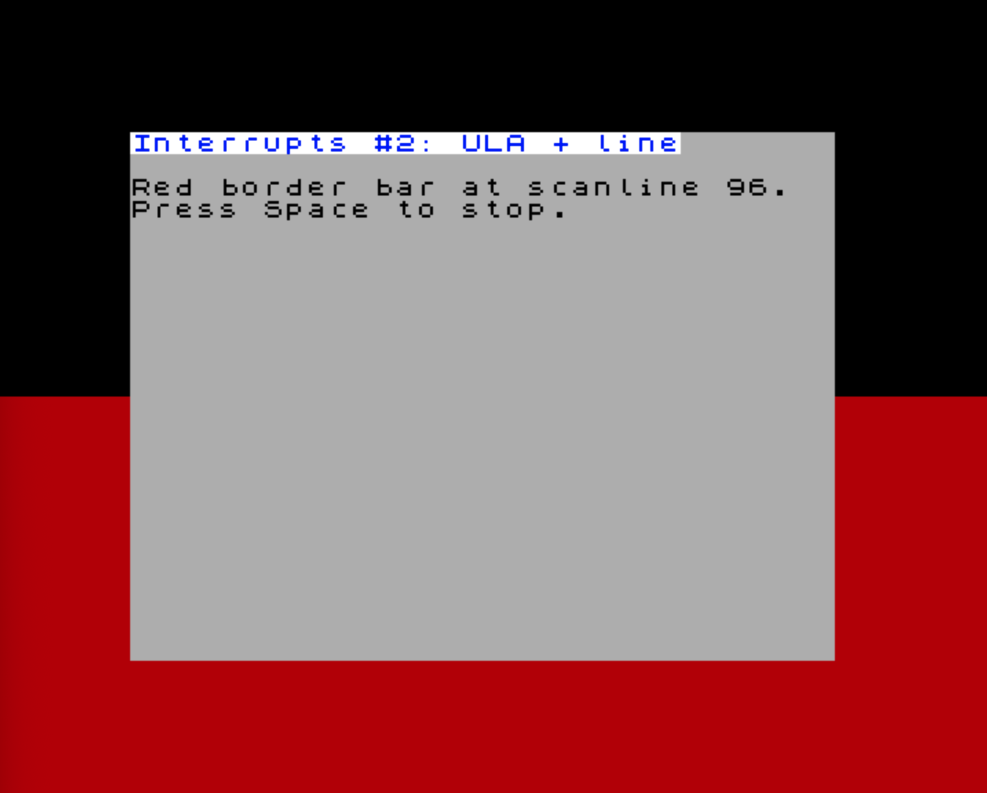
@Title_TwoSources
.defn "Interrupts #2: ULA + line"
@Instr_TwoSources
.defm "Red border bar at scanline 96.\x0d"
.defn "Press Space to stop.\x0d\x0d"Try the InterruptsDemo.TwoSources example.
The two ISRs run independently. The line ISR fires when the raster reaches scanline 96 and paints the border red. The ULA ISR fires at the frame interrupt and resets the border to black. Each handler clears its own readable status bit and returns with EI; RETI; the RETI is what releases that source from the hardware IM2 in-service state. The visible result is a red band across the lower half of the border. No polling, no shared dispatch code, no test in either handler — the priority controller selected the ISR from the vector byte.
Writing a Clean ISR
A few rules of thumb that apply to every ISR you’ll ever write on the Next.
Save what you touch
The interrupted code expects every register to come back unchanged. The easy way is push/pop for the registers you use:
@SomeIsr
    push af
    push bc
    push hl
    ; ... handler body ...
    pop hl
    pop bc
    pop af
    ei
    reti
For very short handlers, EX AF,AF' plus EXX saves the entire main register set in 2 bytes / 8 T-states:
@FastIsr
    ex af,af'
    exx
    ; ... handler body uses A', BC', DE', HL' freely ...
    exx
    ex af,af'
    ei
    reti
The shadow registers are not used by most code, so this is safe — but it’s not re-entrant, because a nested interrupt would corrupt the shadow set. Most ISRs leave interrupts disabled (the default after entry) and EI; RETI at the end, which avoids re-entry naturally.
Acknowledge before you EI
Because /INT is level-sensitive (see above), you must make the source non-requesting before normal interrupts resume. In legacy pulse mode, that usually means clearing the pending bit in NR $C8–$CA before EI. In hardware IM2 mode, RETI releases the daisy-chain in-service state; clearing the matching status bit is still good practice and keeps the same ISR shape useful in both modes.
The order is always: do the work, clear the status, EI, RETI.
@CtcIsr
    push af
    ; ... handler body ...
    nextreg NR_INT_STATUS_1,%00000001   ; ACK CTC channel 0
    pop af
    ei
retiRETI, RETN, and RET — what’s the difference?
At the machine-code level, RETI (Return from Interrupt) and RET do almost the same thing: both pop the top two bytes from the stack into PC and resume execution there. You might reasonably ask: why isn’t RET enough?
The answer is the interrupt daisy chain. The Z80 family was designed to work with companion chips — the Z80 CTC, Z80 PIO, Z80 SIO — chained together so that only the highest-priority device asserting /INT actually gets serviced. Each chip in the chain has an IEI (Interrupt Enable In) and IEO (Interrupt Enable Out) pin. When a chip takes control of the bus for its interrupt acknowledge cycle, it blocks its IEO, preventing any lower-priority chip further down the chain from asserting. The chain stays blocked for the entire duration of the ISR.
RETI exists to release that lock. Classic Z80 peripheral chips watch the instruction stream and recognise the two-byte opcode ED 4D as “interrupt service routine complete”. The Next does the same kind of decode in FPGA fabric: when it sees RETI, the currently serviced hardware-IM2 source is allowed to leave the in-service state, re-opening the chain for lower-priority interrupts.
A plain RET returns the CPU to the interrupted code correctly, but it never generates the daisy-chain release signal. On a system with chained Z80 peripherals, using RET instead of RETI means the chain stays permanently blocked after the first ISR — lower-priority peripherals can never assert their interrupt again.
On the ZX Spectrum Next the hardware IM2 controller emulates this daisy-chain protocol in FPGA fabric, so RETI is equally important: it tells the controller the current ISR is done and allows lower-priority pending interrupts to be dispatched.
RETN (Return from NMI) has a different job. When an NMI fires, the Z80 saves the current IFF1 into IFF2 and then clears IFF1 — interrupts are disabled for the NMI handler. RETN copies IFF2 back into IFF1, restoring the interrupt-enabled state that existed before the NMI. A plain RET would leave IFF1 cleared, so maskable interrupts would stay permanently disabled after any NMI. RETN is therefore mandatory at the end of every NMI handler.
Usually EI, Then RETI
RETI does not re-enable interrupts on the Z80; it informs the daisy chain that the current ISR is complete. If you want normal interrupt processing to resume after the handler, use EI immediately before RETI. The one-instruction EI delay protects the RETI from re-entering the handler. If a handler deliberately wants to return with maskable interrupts disabled, it may omit EI — but that should be an explicit design choice.
Keep it short
Every cycle spent in an ISR is a cycle the main code isn’t running. The line interrupt budget on a 50 Hz frame is about 64 µs per scanline at 3.5 MHz — not much. Long handlers (audio mixing, sprite updates) are usually deferred: the ISR sets a flag and the main loop does the heavy work.
Disable what you don’t need
The status registers report any source that has ever fired since last cleared, even if its enable bit is 0. After installing your IM2 setup, write 0 to the enable bits you don’t want, and clear all status bits with a $FF write to NR $C8/$C9/$CA. This avoids ghost interrupts from previously enabled sources.
Restore IM1 before exit
The ROM expects IM1 with its handler at $0038. If your program is going to return to BASIC or to NextZXOS, switch back before doing so:
    di
    nextreg NR_INT_EN_0,1
    nextreg NR_INT_CONTROL,0
    im 1
    ei
    ret
Forgetting this is a classic source of “the program returned, but the keyboard doesn’t work any more” bugs.
Maskable vs. Non-Maskable
Everything we’ve discussed so far uses the maskable /INT line. The non-maskable /NMI line is rarely interesting for application code:
- It fires on the Multiface button on hardware that has one.
- The divMMC button can also generate NMI on systems where divMMC is wired in.
- The Next can generate NMI in software via NR
$02(used for soft reset and the divMMC menu).
NMI always dispatches to address $0066, regardless of IM mode. That address is in the ROM and the firmware has its own handler — usually it pops up the Multiface or NextZXOS menu. Application programs almost never override it.
If you do need to capture NMIs (for example, a debugger that wants to break on Multiface press), the Next provides:
$C2/$C3— the NMI return address is captured here on every NMI acknowledge cycle.$C0bit 3 — “stackless NMI mode”: the return address goes to NextRegs$C2/$C3instead of being pushed on the stack. The matchingRETNreads it back from there. This avoids stack corruption when NMI fires in code that doesn’t have a valid stack — useful for debug and reset paths.
For the rest of the book we treat NMI as “the firmware’s problem” and focus on /INT.
Where Next
Interrupts are the connecting tissue for nearly every later chapter. With the IM2 setup pattern in your toolbox, the following chapters can each focus on what makes their hardware interesting and just say “enable the source in NR $C5 and provide an ISR”:
- The CTC — uses CTC channel interrupts to drive periodic ticks. Builds directly on the priority table from this chapter.
- zxnDMA — the DMA-end interrupt, plus the
$CC/$CD/$CEmirror NextRegs that let you decide which interrupts are allowed to interrupt a DMA in progress. - Layer 2 and the rest of the video chapters — every one of them assumes you can install a frame or line interrupt without ceremony. Now you can.
- The UART and the ESP and The Real-Time Clock and I²C — both are interrupt-driven in any non-trivial use.
If the priority table feels abstract right now, that’s expected: we’ve only enabled two sources so far. By the end of the CTC chapter you’ll have wired in four, and the dispatch model will feel like second nature.