The CTC: Counter/Timer Circuit
You just wrote a carefully optimized inner loop — maybe a software sprite renderer, maybe a decompression routine — and now you want to know exactly how fast it runs. Not approximately, not “it feels smooth,” but a precise measurement in microseconds. You could count T-states by hand, walking through each instruction with a pencil and the Z80 timing tables. That works for ten instructions. It does not work for a hundred, and it definitely doesn’t work for code with conditional branches, memory contention, and wait states.
The ZX Spectrum Next has a better answer: the CTC (Counter/Timer Circuit). It’s a free-running hardware timer that ticks at a fixed 28 MHz regardless of what the CPU is doing or what speed it’s running at. Set up a channel, read the counter before your code, read it after, subtract — and you have a precise elapsed time. No T-state counting. No guesswork.
But the CTC isn’t just a stopwatch. It’s a full Zilog Z80 CTC with four independently programmable channels, each operating as either a timer or a counter. Channels can cascade through their ZC/TO (Zero Count / Time Out) outputs, extending timing range from microseconds to tens of milliseconds. And each channel can fire interrupts, which means you can build periodic tick systems, audio sample clocks, or timeout watchdogs — all in hardware.
What this chapter assumes. You should already be comfortable with
IN/OUTand NextRegs (I/O Ports and NextRegs). The interrupt sections at the end build on the Z80’s IM2 mode and the Next’s hardware IM2 controller, both covered in Interrupts.
The following sections start with the fundamentals, build up to practical timing code, and finish with interrupt-driven patterns. If you only care about measuring code speed, start at “Measuring Execution Time”; the two sections after it cover longer timing windows and accuracy trade-offs. Understanding the underlying mechanics will help you troubleshoot the inevitable “why is my counter reading wrong?” moments.
What the CTC Is (and Isn’t)
The CTC on the Next is a standard Zilog Z80 CTC — the same chip design that appeared alongside the Z80 CPU in 1976. If you’ve ever programmed a CTC on a CP/M machine, an MSX, or an Amstrad CPC, the programming model is identical. The classic Zilog datasheet (Z8430 CTC Technical Manual) applies directly, with a few Next-specific wrinkles we’ll cover.
The Next currently implements 4 CTC channels (numbered 0 through 3). The FPGA design allocates port space for 8 channels, but channels 4–7 are hardwired to return zero on reads and ignore writes. Don’t waste time trying to configure them.
Here’s what each channel can do:
- Timer mode: Divide the 28 MHz system clock by a programmable prescaler (÷16 or ÷256), then count down from a loaded value. When the count hits zero, it fires a ZC/TO pulse and reloads.
- Counter mode: An external signal (from another channel’s ZC/TO output) directly decrements the counter. No prescaler involved.
- Interrupt generation: Each channel can trigger an interrupt on ZC/TO. The Next’s hardware IM2 system routes these to specific vector addresses.
What the CTC is not: it’s not a high-resolution cycle counter like the x86 RDTSC instruction. You can’t read a 64-bit timestamp. Each channel has an 8-bit down-counter, readable via a port read. That’s 256 distinct values. For longer measurements, you cascade channels or count ZC/TO interrupts. It takes a little more setup than a modern performance counter, but it’s entirely adequate for profiling Z80 code.
Enabling the CTC
The CTC ports are enabled by default at reset — NextReg $85 bit 3 controls the gate, and the reset value ($0F) has it set. Unless something in your code has cleared that bit, you don’t need to do anything:
    ; Check/ensure CTC ports are enabled (usually unnecessary)
    ld a,$85
    ld bc,$243B
    out (c),a                ; Select NextReg $85
    ld bc,$253B
    in a,(c)                 ; Read current value
    or $08                   ; Set bit 3 (CTC port enable)
    out (c),a                ; Write back
In practice, you’ll almost never need this. But if your CTC reads are returning $FF when you expect counter values, this is the first thing to check.
Channel Port Addresses
Each channel has its own I/O port. The channel number is encoded in address bits A10:A8:
| Channel | Port Address | Bits A10:A8 |
|---|---|---|
| 0 | $183B | 000 |
| 1 | $193B | 001 |
| 2 | $1A3B | 010 |
| 3 | $1B3B | 011 |
| 4–7 | $1C3B–$1F3B | 100–111 (reserved) |
Writing to a channel port sends a control word or time constant. Reading from a channel port returns the current value of the 8-bit down-counter.
The Control Word
Every CTC channel is configured by writing a single control byte followed (optionally) by a time constant byte. The control byte is identified by D0=1:
| Bit | Name | Value = 0 | Value = 1 |
|---|---|---|---|
| D7 | Interrupt | Disabled | Enabled |
| D6 | Mode | Timer | Counter |
| D5 | Prescaler | ÷16 | ÷256 (timer mode only) |
| D4 | Trigger edge | Falling | Rising |
| D3 | Trigger start | Start immediately | Wait for trigger (timer mode) |
| D2 | Time constant | Not following | Time constant byte follows |
| D1 | Software reset | — | Reset channel |
| D0 | Control word | (this is a vector byte) | Control word |
A few things to notice:
- D2 must be set on the first write after a hard reset (power-on). The channel sits in a reset state waiting specifically for a control word with D2=1, which tells it “a time constant byte is coming next.” Without D2=1, the channel never leaves the reset state.
- D1 (soft reset) forces the channel back to its initial state. If the channel is in an unknown state — maybe you inherited it from someone else’s code — write the control word twice with D1=1 and D2=0 to guarantee a clean reset. The first write might be interpreted as a time constant if the channel was expecting one; the second write is guaranteed to be read as a control word.
- D5 (prescaler) is only relevant in timer mode. In counter mode, the external trigger directly decrements the count — the prescaler is bypassed.
- D4 (trigger edge) has a subtle hardware side-effect: changing D4 counts as a clock edge internally. Keep this in mind if you’re reconfiguring a running channel.
Writing a Control Word and Time Constant
Here’s the typical two-write sequence to configure a channel:
    ; Configure Channel 0 as a timer, prescaler ÷16, start immediately
    ld bc,$183B             ; Channel 0 port
    ld a,%00000101          ; D0=1 (control word)
                            ; D1=0 (no reset), D0=1 (control word)
                            ; D2=1 (time constant follows)
                            ; D3=0 (start immediately)
                            ; D4=0 (trigger on falling edge)
                            ; D5=0 (prescaler ÷16)
                            ; D6=0 (timer mode)
                            ; D7=0 (no interrupt)
    out (c),a               ; Send control word

    ld a,200                ; Time constant: count down from 200
    out (c),a               ; Send time constant — channel starts running
After the time constant byte is written, the channel transitions to the RUNNING state and begins counting down. In timer mode with D3=0 (start immediately), this happens on the next clock cycle. With D3=1, the channel waits for a trigger edge before starting.
The time constant is not a one-use starting value. The CTC stores it internally. Whenever the counter reaches zero and emits its ZC/TO pulse, the channel automatically reloads the counter from that saved value and continues.
Timer Mode: How the Countdown Works
In timer mode, the channel divides the 28 MHz system clock using the prescaler, then decrements the counter once per prescaler output pulse:
- Prescaler input: 28 MHz system clock (not the CPU clock — this is important!)
- Prescaler divides by 16 (D5=0) or 256 (D5=1)
- Each prescaler output decrements the 8-bit counter by 1
- When the counter reaches zero: ZC/TO fires (one-cycle pulse), the counter reloads from the time constant register, and counting continues
Timing Math
The prescaler and time constant together determine the tick rate and period:
Prescaler ÷16 (D5=0):
- One counter tick = 16 / 28 MHz = ~571.4 ns
- Maximum period (time constant = 256): 256 × 571.4 ns ≈ 146.3 μs
- Minimum period (time constant = 1): 571.4 ns
Prescaler ÷256 (D5=1):
- One counter tick = 256 / 28 MHz = ~9.143 μs
- Maximum period (time constant = 256): 256 × 9.143 μs ≈ 2.34 ms
- Minimum period (time constant = 1): 9.143 μs
A time constant of 0 is treated as 256 — the full 8-bit range.
Critical note: The CTC clock input is always the 28 MHz base system clock. It is not affected by NextReg
$07(CPU speed). Whether you’re running at 3.5 MHz, 7 MHz, 14 MHz, or 28 MHz, the CTC ticks at the same rate. This is actually what makes it perfect for measuring code speed — the timer runs at a fixed rate while the CPU speed varies, so you’re measuring wall-clock time, not T-states.
Counter Mode: External Triggers
In counter mode (D6=1), the prescaler is bypassed entirely. Instead, an external signal decrements the counter directly. On the Next, that “external signal” is the ZC/TO output of the preceding channel in the daisy chain:
| Channel | Trigger Source |
|---|---|
| 0 | Channel 3’s ZC/TO |
| 1 | Channel 0’s ZC/TO |
| 2 | Channel 1’s ZC/TO |
| 3 | Channel 2’s ZC/TO |
Each ZC/TO pulse from the upstream channel decrements the downstream channel’s counter by one. This is how you cascade channels for wider timing ranges — more on this in the measurement section.
Reading the Counter
Reading a channel’s port returns the current value of the 8-bit down-counter:
    ld bc,$183B             ; Channel 0 port
    in a,(c)                ; A = current counter value (0–255)
The value counts down from the loaded time constant. If you loaded 200 and read back 180, that means 20 ticks have elapsed since the counter was loaded.
This is the core primitive for timing: read before, read after, subtract.
Measuring Execution Time
This is the section you came here for. Let’s build the smallest practical code-timing setup: one CTC channel used as a stopwatch for short code blocks.
The Basic Idea
- Configure a CTC channel as a timer with a known prescaler
- Load a time constant (typically 0 = 256 for maximum headroom)
- Read the counter: this is your “start” value
- Run the code you want to measure
- Read the counter again: this is your “end” value
- Subtract: elapsed ticks = start − end (the counter counts down)
- Multiply by the tick duration to get elapsed time
Single-Channel Timing (Short Code Blocks)
For code blocks that complete within a single counter period, one channel is enough. Using prescaler ÷16 with time constant 0 (= 256) gives you a measurement window of ~146 μs — that’s about 512 T-states at 3.5 MHz, enough for most inner loops.
CTC_CH0     equ $183B

; === Set up Channel 0: timer, prescaler ÷16, start immediately ===
    ld bc,CTC_CH0
    ld a,%00000101          ; Timer mode, prescaler ÷16, time const follows
    out (c),a
    ld a,0                  ; Time constant = 256 (0 means 256)
    out (c),a

; === Measure ===
    in a,(c)                ; Read counter BEFORE
    ld (startCount),a       ; Save start value
    ; ---- The code under test begins here ----

    ; ... your code block here ...

    ; ---- The code under test ends here ----
    in a,(c)                ; Read counter AFTER
    ld b,a                  ; B = end value
    ld a,(startCount)       ; A = start value
    sub b                   ; A = elapsed ticks (start − end, since it counts down)
    ld (elapsedTicks),a     ; Save result

; === Convert to time ===
; Each tick = 16 / 28 MHz ≈ 571.4 ns
; Multiply by 571 for nanoseconds (approximately)
; Or just interpret in ticks and do the conversion off-machine

    ; ...
    ret

startCount:  .db 0
elapsedTicks: .db 0
Watch out for wraparound! If the counter wraps past zero during your measurement, the subtraction still works correctly — as long as the code doesn’t take longer than one full period (256 ticks). The 8-bit unsigned subtraction handles a single wraparound naturally. If the code takes longer than 256 ticks, you’ll get an incorrect result. Use the cascaded setup below for longer blocks.
Overhead Accounting
The IN instruction itself takes time — 12 T-states at 3.5 MHz. But remember, the CTC doesn’t tick in T-states; it ticks in 28 MHz clocks (÷ prescaler). At prescaler ÷16:
- 12 T-states × 8 clocks/T-state (at 3.5 MHz) = 96 system clocks = 6 CTC ticks
- The
LD (nn), Aafter the firstINadds another ~4 ticks
So your measurement has a fixed overhead of roughly 10 ticks (about 5.7 μs). If you need to subtract this, measure an empty block (no code between the two IN instructions) and use that as your baseline.
At 28 MHz CPU speed, 12 T-states = 12 system clocks = 0.75 CTC ticks at ÷16 prescaler. The overhead is much smaller at higher CPU speeds.
Resolution Floor: The Minimum Measurable Interval
You might be wondering: is ~571.4 ns truly the smallest time interval the CTC can detect? Yes — and it comes with an important implication.
The counter only decrements once every 16 system clock cycles (at prescaler ÷16). That 16-clock window is a blind spot. If the code under test completes within a single 16-clock window — faster than ~571 ns — the counter will not have moved between the two IN reads, and you will read 0 elapsed ticks even though real time passed. There is no way around this with the CTC alone: the prescaler is internal and not directly readable.
At 28 MHz, 16 system clocks is 16 instructions if every instruction takes 1 clock (like NOP). So measuring a tight 10-instruction loop at full CPU speed may return 0. At 3.5 MHz, 16 system clocks is only 2 T-states worth of execution — so at slow CPU speeds, sub-tick blindness rarely matters.
In practice, the measurement overhead itself (~10 ticks at 3.5 MHz, as computed above) means the smallest useful measurement window is already several microseconds wide. Code that completes in under ~571 ns is genuinely difficult to profile with a CTC; counting T-states by hand is the right tool for those cases.
Summary:
- CTC tick resolution: ~571.4 ns (prescaler ÷16), ~9.14 μs (prescaler ÷256)
- Code that runs faster than one tick: returns 0 elapsed ticks (not detectable)
- Practical minimum useful measurement: ~5.7 μs (the overhead of the bracketing instructions at 3.5 MHz)
- For sub-microsecond profiling at 28 MHz: count T-states manually from the instruction timing tables
Extending the Measurement Range
One CTC channel gives excellent resolution, but only an 8-bit timing window. For longer routines, keep Channel 0 as the fine timer and cascade additional channels as coarse counters.
Cascaded Timing (Longer Code Blocks)
For code that runs longer than ~146 μs (at prescaler ÷16), you need more than 8 bits of timing resolution. The solution is to cascade two channels: Channel 0 runs as a timer and its ZC/TO output triggers Channel 1 in counter mode. This effectively creates a 16-bit counter.
CTC_CH0     equ $183B
CTC_CH1     equ $193B

; === Set up Channel 0: timer, prescaler ÷16, time constant = 256 ===
; ZC/TO fires every 256 × 16 / 28 MHz ≈ 146.3 μs
    ld bc,CTC_CH0
    ld a,%00000101          ; Timer mode, prescaler ÷16, time const follows
    out (c),a
    ld a,0                  ; Time constant = 256
    out (c),a

; === Set up Channel 1: counter mode, triggered by Ch0's ZC/TO ===
; Each Ch0 ZC/TO decrements Ch1 by 1
    ld bc,CTC_CH1
    ld a,%01000101          ; Counter mode (D6=1), time const follows
    out (c),a
    ld a,0                  ; Time constant = 256
    out (c),a

; === Measure ===
; Read both channels: Ch1 (coarse) then Ch0 (fine)
    ld bc,CTC_CH1
    in a,(c)
    ld d,a                  ; D = coarse count (Ch1)
    ld b,high(CTC_CH0)      ; C is still $3B — only B needs to change
    in a,(c)
    ld e,a                  ; E = fine count (Ch0)
    ld (startCoarse),de     ; Save 16-bit start value

    ; ---- Code under test ----

    ; ... your code block here ...

    ; ---- End of code under test ----

    ld bc,CTC_CH1
    in a,(c)
    ld d,a                  ; D = coarse count (Ch1)
    ld b,high(CTC_CH0)      ; C is still $3B — only B needs to change
    in a,(c)
    ld e,a                  ; E = fine count (Ch0)

; === Calculate elapsed ===

; Elapsed = startDE − endDE (both channels count down)
    ld hl,(startCoarse)     ; H = start coarse, L = start fine
    or a                    ; clear carry flag
    sbc hl,de               ; HL = start − end (elapsed ticks, since counters count down)
    ex de,hl                ; DE = elapsed ticks

; DE now holds the 16-bit elapsed count:
;   Total system clocks ≈ ((D × 256) + (256 − E)) × 16
;   But more precisely: elapsed fine ticks in E, elapsed coarse periods in D
;   Time ≈ (D × 256 + (start_fine − end_fine)) × 571.4 ns

    ld (elapsedCoarse),de
    ret

startCoarse: .dw 0
elapsedCoarse: .dw 0
The cascaded setup gives you a 16-bit timing window: 256 × 256 = 65,536 ticks at prescaler ÷16, which is about 37.4 milliseconds — more than two full frames at 50 Hz. That’s enough to time essentially any subroutine.
Overhead Accounting for Two-Channel Cascaded Measurement
The two-channel snapshot requires four IN instructions instead of two — one pair for Ch1 (coarse) and one pair for Ch0 (fine) — with LD BC setup and register stores in between. All of that burns CTC ticks before and after your code.
At 3.5 MHz with prescaler ÷16, here’s what accumulates on each side of the code under test:
Before the code (after the Ch1 start read):
LD D,A+LD B,high(CTC_CH0)+IN A,(C)+LD E,A+LD (startCoarse),DE- 4 + 7 + 12 + 4 + 20 = 47 T-states × 8 clocks/T-state ÷ 16 = ~24 CTC ticks
After the code (before the Ch0 end read):
LD BC,CTC_CH1+IN A,(C)+LD D,A+LD B,high(CTC_CH0)- 10 + 12 + 4 + 7 = 33 T-states = ~17 CTC ticks
Plus the two boundary IN instructions themselves: 12 + 12 T-states = 12 CTC ticks
Total overhead: ~53 CTC ticks ≈ 30 μs at 3.5 MHz — roughly 5× the single-channel overhead. That sounds like a lot, but the context is very different: the two-channel setup is for code blocks longer than ~146 μs. A 30 μs overhead is less than 0.1% of the 37 ms measurement range. Measure an empty block (no code between the start and end snapshots) once to capture the baseline, then subtract it from all subsequent results.
At 28 MHz, those same 104 T-states of overhead instructions take only ~7 CTC ticks (~4 μs) because each T-state equals just one system clock at full CPU speed.
A note on snapshot simultaneity: The two reads within each snapshot are not taken at the same instant — roughly 13 CTC ticks (~7.4 μs) separate reading Ch1 from reading Ch0. In practice this is negligible against a 37 ms window, but in an unlikely edge case where Ch0 wraps between the two reads, the elapsed calculation will be off by one coarse period. This is the price of reading two 8-bit counters that weren’t designed to be latched simultaneously.
Three and Four Channel Chains
The same principle keeps going. Because the ZC/TO connections run Ch0→Ch1→Ch2→Ch3 in sequence, you can stack three or all four channels to get timing ranges that grow by 256× with every channel you add — while keeping the ~571 ns tick resolution of the ÷16 prescaler on Channel 0.
Three channels (Ch0 timer ÷16 → Ch1 counter → Ch2 counter): 256³ × 571.4 ns ≈ 9.6 seconds at ~571 ns per fine tick.
Four channels (Ch0 timer ÷16 → Ch1 counter → Ch2 counter → Ch3 counter): 256⁴ × 571.4 ns ≈ 40.9 minutes — practically unlimited for any code timing purpose.
Adding Channel 2 to the two-channel setup from above requires only two additional OUT instructions at initialization:
CTC_CH2     equ $1A3B
; (Channels 0 and 1 already configured as shown above)

; === Add Channel 2: counter mode, triggered by Channel 1's ZC/TO ===
    ld bc,CTC_CH2
    ld a,%01000101          ; Counter mode (D6=1), time constant follows
    out (c),a
    ld a,0                  ; Time constant = 256
    out (c),a
For a four-channel chain, configure Channel 3 the same way (port $1B3B, same control byte).
The snapshot and elapsed calculation extend the 2-channel pattern by reading one extra channel per level. Read from the coarsest channel down to the finest, store three (or four) bytes, then subtract using SUB for the fine byte and SBC for each subsequent byte to propagate the borrow:
; === Three-channel snapshot ===
    ld bc,CTC_CH2
    in a,(c)
    ld (ctcStart+2),a       ; Coarsest byte
    ld b,high(CTC_CH1)      ; C is still $3B
    in a,(c)
    ld (ctcStart+1),a       ; Medium byte
    ld b,high(CTC_CH0)      ; C is still $3B
    in a,(c)
    ld (ctcStart+0),a       ; Fine byte

    ; ---- Code under test ----

    ld bc,CTC_CH2
    in a,(c)
    ld (ctcEnd+2),a
    ld b,high(CTC_CH1)      ; C is still $3B
    in a,(c)
    ld (ctcEnd+1),a
    ld b,high(CTC_CH0)      ; C is still $3B
    in a,(c)
    ld (ctcEnd+0),a

; === elapsed = start − end (correct, 24-bit) ===
    ld a,(ctcEnd+0)         ; end fine → temp
    ld b,a
    ld a,(ctcStart+0)       ; start fine
    sub b                    ; A = start_fine − end_fine, carry = borrow
    ld (ctcElapsed+0),a

    ld a,(ctcEnd+1)
    ld b,a
    ld a,(ctcStart+1)
    sbc a,b                 ; start_medium − end_medium − borrow
    ld (ctcElapsed+1),a

    ld a,(ctcEnd+2)
    ld b,a
    ld a,(ctcStart+2)
    sbc a,b                 ; start_coarse − end_coarse − borrow
    ld (ctcElapsed+2),a

; ctcElapsed is now a 24-bit down-count in little-endian order:
;   elapsed ticks = ctcElapsed[2] × 65536 + ctcElapsed[1] × 256 + ctcElapsed[0]
;   wall-clock time ≈ elapsed_ticks × 571.4 ns

ctcStart:   .db 0, 0, 0
ctcEnd:     .db 0, 0, 0
ctcElapsed: .db 0, 0, 0
Overhead Accounting for Three and Four Channel Chains
Each additional channel in the chain adds one more IN A,(C) read (~6 ticks) and LD (nn), A store (~6.5 ticks) to each snapshot half. The new coarsest channel needs a full LD BC setup (~5 ticks), while all others use the cheaper LD B, high(...) (~3.5 ticks) — roughly 32–36 extra CTC ticks per channel added (both snapshot halves combined).
At 3.5 MHz with prescaler ÷16:
| Chain depth | Total overhead | Approx. wall-clock | As % of max range |
|---|---|---|---|
| 2 channels | ~53 ticks | ~30 μs | < 0.1% |
| 3 channels | ~88 ticks | ~50 μs | 0.0005% |
| 4 channels | ~120 ticks | ~69 μs | effectively zero |
At these scales the overhead is genuinely irrelevant. A 54 μs overhead on a 9.6-second window doesn’t affect any measurement you’d care about. The methodology stays the same as always: run an empty block once, record the baseline tick count, subtract from every subsequent measurement. At 28 MHz, all these overhead figures shrink 8× — 3-channel becomes ~12 ticks, 4-channel ~16 ticks.
Snapshot timing gap grows with depth: In a three-channel snapshot, the Ch2 (coarse) read and the Ch0 (fine) read are separated by about 26 CTC ticks (~14.9 μs). For a four-channel snapshot that gap grows to ~39 CTC ticks (~22 μs). Against a 9.6-second or 40.9-minute window, this is noise.
There is one subtlety worth understanding: always read from the coarsest channel first (which is what the code above does). If you accidentally reversed the order and read Ch0 fine first and Ch2 coarse last, a Ch0 wrap that occurs between the two reads would corrupt the measurement. With coarsest-first ordering, any wrap that happens between reads affects only the fine channel — and the maximum error is bounded to one Ch0 period (~146 μs). With finest-first ordering, the same wrap could appear as an error of nearly one Ch2 period (~37 ms). Coarsest-first keeps the worst case small.
Why prefer 3-channel ÷16 over 2-channel ÷256?
Both approaches target longer measurement windows, but they make very different trade-offs:
| Approach | Max range | Resolution |
|---|---|---|
| 2 channels, prescaler ÷256 | ~599 ms | ~9.14 μs per tick |
| 3 channels, prescaler ÷16 | ~9.6 s | ~571 ns per tick |
The 3-channel ÷16 chain is both longer and more precise. The resolution advantage is 16× — you can see a single 28 MHz instruction cycle’s contribution where ÷256 would round it away entirely. The only cost is one extra channel. If you have a spare channel and need both range and resolution, 3-channel ÷16 is the better choice.
Using Prescaler ÷256 for Even Longer Periods
If you need to time something truly long (say, a full-screen rendering pass), switch Channel 0 to prescaler ÷256. This changes the numbers:
- Single channel: 256 × 9.143 μs ≈ 2.34 ms per period
- Cascaded: 256 × 256 × 9.143 μs ≈ 599 ms — half a second!
The trade-off is resolution: each tick is now ~9.1 μs instead of ~571 ns. For a 28 MHz CPU, that’s about 256 system clocks per tick — you can’t distinguish individual instructions anymore, but you can easily time subroutines and rendering passes.
; Channel 0: timer, prescaler ÷256 (D5=1), time constant = 256
    ld bc,$183B
    ld a,%00100101          ; Timer, prescaler ÷256, time const follows
    out (c),a
    ld a,0                  ; Time constant = 256
    out (c),a
Demo: Measuring Time
This demo packages the two-channel cascaded setup from the previous section into a small reusable timing helper. Channel 0 supplies the fine ÷16 timer ticks, and Channel 1 counts Channel 0 wraparounds. Each tick is still about 571 ns, so you can convert the printed value to wall-clock time with the same math used in the earlier cascaded-timing snippets.
The helper returns the elapsed 16-bit count in DE. The demo exchanges it into HL only because the display helper prints HL.
Each measured block follows the same shape:
    ; Prepare the 16-bit CTC stopwatch
    call Timing.SetupCtc16
    call Timing.StartMeasure

    ; ---- Code under test ----

    ; Read the elapsed 16-bit tick count in DE
    call Timing.GetMeasuredCounter
    ex de,hl
    Display.Ink(Color.Blue)
    Display.PrintHLDecimal()
SetupCtc16 is the setup code from “Cascaded Timing (Longer Code Blocks)” packaged as a subroutine. StartMeasure snapshots the current coarse/fine counter pair. GetMeasuredCounter snapshots it again, subtracts the two down-counting values, and returns the elapsed tick count in DE. The routine also stores the new snapshot as the next start value, which is handy if you later want lap-style measurements.
.module Timing

CTC_CH0     .equ $183b
CTC_CH1     .equ $193b
CTC_CH2     .equ $1a3b
CTC_CH3     .equ $1b3b

; The counter value when measuring starts
Counter_Start
    .defw 0

; Sets up the CTC (CH0 and CH1) for 16-bit counting.
; The counter starts the countdown immediately.
SetupCtc16
; === Set up Channel 0: timer, prescaler ÷16, time constant = 256 ===
; ZC/TO fires every 256 × 16 / 28 MHz ≈ 146.3 μs
    ld bc,CTC_CH0
    ld a,%00000101          ; Timer mode, prescaler ÷16, time const follows
    out (c),a
    ld a,0                  ; Time constant = 256
    out (c),a

; === Set up Channel 1: counter mode, triggered by Ch0's ZC/TO ===
; Each Ch0 ZC/TO decrements Ch1 by 1
    ld b,high(CTC_CH1)
    ld a,%01000101          ; Counter mode (D6=1), time const follows
    out (c),a
    ld a,0                  ; Time constant = 256
    out (c),a
    ret

; Saves the current counter value (start counter).
StartMeasure
    ld bc,CTC_CH1
    in a,(c)
    ld d,a                  ; D = coarse count (Ch1)
    ld b,high(CTC_CH0)
    in a,(c)
    ld e,a                  ; E = fine count (Ch0)
    ld (Counter_Start),de   ; Save 16-bit start value
    ret

; Gets the measured value since the last start.
GetMeasuredCounter
    ld bc,CTC_CH1
    in d,(c)
    ld b,high(CTC_CH0)
    in e,(c)

; Elapsed = start − end (both channels count down)
    ld hl,(Counter_Start)   ; H = start coarse, L = start fine
    ld (Counter_Start),de   ; Next time use this start value
    or a                    ; clear carry flag
    sbc hl,de               ; HL = start − end (elapsed ticks, since counters count down)
    ex de,hl                ; DE = elapsed ticks
    ret

; Decrements BC in a loop until it reaches 0
@DelayWithBc
    dec bc
    ld a,b
    or c
    ret z
    jr @DelayWithBc

Delay .macro(value)
    push bc
    ld bc,{{value}}
`loop
    call @DelayWithBc
    pop bc
    .endm

.endmodule
The demo reuses the same measurement wrapper around three different code blocks:
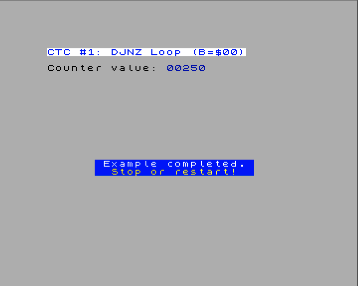
CtcDemos.Measure1 measures a full DJNZ loop. Loading B with zero gives 256 iterations, because DJNZ decrements first and stops only when the result becomes zero.
    ld b,$00
`loop
djnz `loopTry the CtcDemos.Measure1 example.
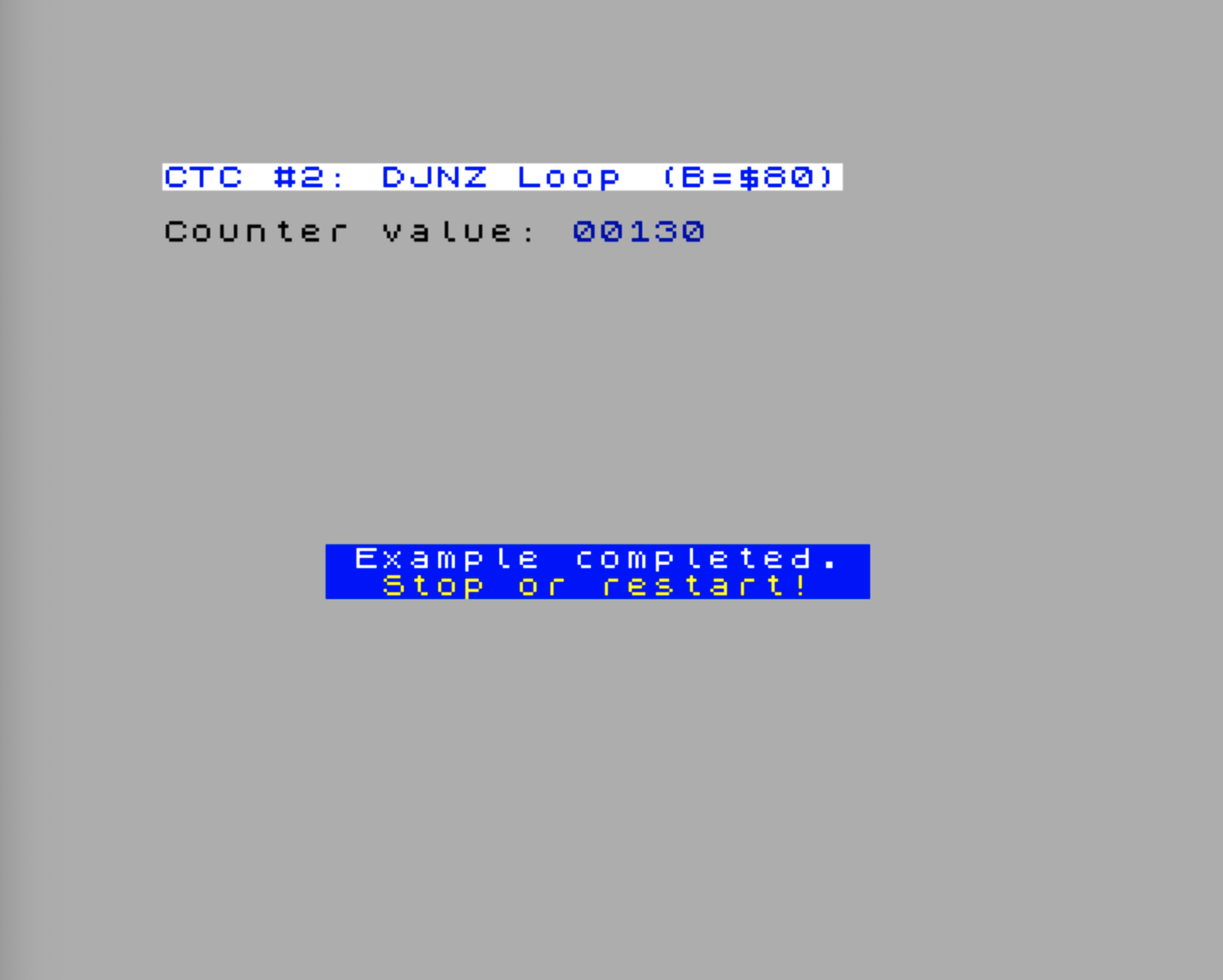
CtcDemos.Measure2 measures the same loop body with fewer iterations:
    ld b,$80
`loop
djnz `loopTry the CtcDemos.Measure2 example.
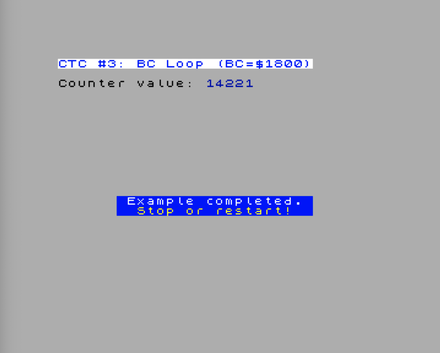
CtcDemos.Measure3 measures a longer BC countdown. The Timing.Delay macro is only a thin wrapper around the helper loop shown above, so the measured block stays readable:
Timing.Delay($1800)Try the CtcDemos.Measure3 example.
Choosing and Interpreting Measurements
Once you have the basic and cascaded setups, the remaining work is choosing the right range and understanding the small errors that come from reading live counters.
Quick Reference: Measurement Ranges
| Setup | Tick Duration | 1 channel | 2 channels | 3 channels | 4 channels |
|---|---|---|---|---|---|
| Prescaler ÷16 | ~571 ns | ~146 μs | ~37.4 ms | ~9.6 s | ~40.9 min |
| Prescaler ÷256 | ~9.14 μs | ~2.34 ms | ~599 ms | ~2.56 min | ~656 min |
CPU Speed and Timing: A Practical Example
Let’s say you have a tight loop that runs in exactly 100 T-states at 3.5 MHz. How many CTC ticks will it consume at each CPU speed?
At 3.5 MHz (1 T-state = 8 system clocks = 285.7 ns):
- 100 T-states = 800 system clocks = 28.57 μs
- At prescaler ÷16: 800 / 16 = 50 CTC ticks
At 7 MHz (1 T-state = 4 system clocks):
- 100 T-states = 400 system clocks = 14.29 μs
- At prescaler ÷16: 400 / 16 = 25 CTC ticks
At 14 MHz (1 T-state = 2 system clocks):
- 100 T-states = 200 system clocks = 7.14 μs
- At prescaler ÷16: 200 / 16 = 12.5 CTC ticks (≈ 12 or 13 depending on alignment)
At 28 MHz (1 T-state = 1 system clock):
- 100 T-states = 100 system clocks = 3.57 μs
- At prescaler ÷16: 100 / 16 = 6.25 CTC ticks (≈ 6 or 7)
The CTC always measures wall-clock time, not instruction time. The same code takes fewer CTC ticks at a higher CPU speed because it actually runs faster. This is exactly what you want for profiling — you’re measuring how long the user waits, not how many instructions the CPU executes.
Choosing Your Setup and Knowing Its Limits
After working through all the variants, here is the practical summary: a decision guide and a list of accuracy quirks worth keeping in mind.
Which setup should you use?
| Situation | Recommendation |
|---|---|
| Code completes in < ~146 μs | Single channel, prescaler ÷16 |
| Code completes in < ~2.3 ms | Single channel, prescaler ÷256 |
| Code completes in < ~37 ms | Two channels, prescaler ÷16 |
| Code completes in < ~600 ms | Two channels, prescaler ÷256 — or three channels ÷16 |
| Code completes in < ~9.6 s | Three channels, prescaler ÷16 |
| Timing a full frame or more | Four channels, prescaler ÷16 |
When in doubt, two channels at ÷16 is the right default. It covers every inner loop and subroutine you’ll normally profile (37 ms is two full 50 Hz frames), gives ~571 ns resolution, and its overhead is under 0.1% of the measurement window. Switch to three or four channels only when you genuinely need to time something that runs for seconds.
Accuracy issues you should know about:
-
Measurement overhead is not zero. The
INinstructions that bracket your code each consume ~6 CTC ticks at 3.5 MHz. The register moves and channel-switch instructions between paired reads add more — see the overhead accounting subsections above for exact figures. Always measure an empty block (nothing between the bracketingINcalls) once and subtract that baseline from every subsequent result. -
Prescaler phase jitter (±1 tick). The prescaler is a free-running internal counter that is not reset when you start a measurement. Depending on where it sits when the opening
INexecutes, the first counted tick may arrive slightly earlier or later than expected. This adds up to ±1 tick (~571 ns at ÷16) of run-to-run jitter. For a single measurement the error is negligible; if you need higher confidence, average several runs. -
Counter wraparound is handled, but only once. 8-bit subtraction
start − endnaturally handles a single wraparound (when the counter crosses zero between the two reads). If the code under test takes longer than one full counter period — 256 ticks at ÷16 ≈ 146 μs — the subtraction will produce a garbage result that is too small, not a negative number or an error. The fix is to add a channel, not to try to detect wraparound in software. -
Multi-channel snapshots are not simultaneous. In a two-channel setup the Ch1 (coarse) and Ch0 (fine) reads are separated by ~13 CTC ticks (~7.4 μs at 3.5 MHz). In a three-channel snapshot, the coarsest and finest reads are ~26 ticks apart. This means Ch0 could wrap between the two reads, throwing the coarse count off by one period. Reading coarsest-first — as every example above does — keeps the worst-case error bounded to one Ch0 period (~146 μs). Reading finest-first would let the same wrap appear as an error of nearly one Ch1 period (~37 ms).
-
Sub-tick blindness. Code that completes faster than one prescaler period — under ~571 ns at ÷16 — will return 0 elapsed ticks regardless of how much real time passed. There is no workaround within the CTC. For sub-microsecond code at 28 MHz, count T-states by hand from the instruction timing tables.
-
The CTC clock does not track CPU speed. This is usually the point — wall-clock time is what matters — but it means the tick count for a given piece of code will change if you change CPU speed via NextReg
$07. A routine that measures 50 ticks at 3.5 MHz will measure 25 ticks at 7 MHz, not because it got faster in terms of instructions, but because it genuinely runs in half the wall-clock time. Always record the CPU speed alongside any CTC measurement.
CTC Interrupts
Each CTC channel can generate an interrupt on its ZC/TO event. The Next’s interrupt system routes CTC interrupts through the hardware IM2 mechanism, which is more flexible (and more convenient) than the classic Z80 IM2 daisy-chain.
Heads-up. This section assumes you’ve already read Interrupts, which covers IM2, the I register, and the Next’s hardware IM2 controller in detail. We only summarise here the parts specific to the CTC.
The Next’s Hardware IM2 Mode
Unlike classic Z80 IM2 where the interrupting device places a vector byte on the data bus, the Next computes IM2 vectors internally based on interrupt priority. You configure this with several NextRegs:
NextReg $C0 — IM2 Vector Configuration:
- Bits [7:5]: Programmable top bits of the interrupt vector
- Bit 0: Hardware IM2 mode enable (1 = enabled)
NextReg $C5 — CTC Interrupt Enable:
- Bits [3:0]: Enable interrupt for CTC channels 0–3 (bit 0 = channel 0)
NextReg $C9 — CTC Interrupt Status:
- Bits [3:0]: Interrupt status for CTC channels 0–3 (write 1 to clear)
Vector Calculation
In hardware IM2 mode, each interrupt source has a fixed priority number. The CTC channels are assigned priorities 3 through 6:
| Channel | Priority | Vector Offset |
|---|---|---|
| 0 | 3 | $06 |
| 1 | 4 | $08 |
| 2 | 5 | $0A |
| 3 | 6 | $0C |
The vector address is: im2TopBits | (priority << 1)
For example, if NR $C0 bits [7:5] = 110 (top bits = $C0):
- CTC Channel 0 vector =
$C0 | $06=$C6 - CTC Channel 1 vector =
$C0 | $08=$C8 - CTC Channel 2 vector =
$C0 | $0A=$CA - CTC Channel 3 vector =
$C0 | $0C=$CC
The CPU reads the ISR address from the vector table at (I × 256 + vector).
Demo: Setting Up a Periodic CTC Interrupt
This demo uses the CTC as a background metronome. Channels 0, 1, and 2 form a cascade; only Channel 2 is allowed to interrupt the CPU. The ISR increments a 16-bit counter, while the main loop keeps moving one attribute byte along screen row 8 and exits when you press Space.
That split is the important pattern: the interrupt does the tiny, time-sensitive job, and the main loop does the visible work. If the ISR starts printing text or painting the screen, it stops being a timer tick and becomes a surprise scheduling problem. Keep it boring. Boring ISRs are good ISRs.
.module CtcInterruptDemo

NR_INT_CONTROL  .equ $c0
NR_INT_EN_0     .equ $c4
NR_INT_EN_1     .equ $c5
NR_INT_STATUS_0 .equ $c8
NR_INT_STATUS_1 .equ $c9

CTC_CH0         .equ $183b
CTC_CH1         .equ $193b
CTC_CH2         .equ $1a3b

VECTOR_TOP_BITS .equ %01100000   ; $60
CTC2_PRIORITY   .equ 5
CTC2_VECTOR     .equ VECTOR_TOP_BITS | (CTC2_PRIORITY << 1) ; $6A

;==========================================================
; CTC interrupt demo: increment a 16-bit counter every 100 ms
;==========================================================
Every100MsCounter
    Display.PrintTitle(@Title)
    Display.PrintText(@Instr)

    di

    ; Keep unrelated interrupt sources quiet for this demo.
    nextreg NR_INT_EN_0,0
    nextreg NR_INT_EN_1,0
    nextreg NR_INT_STATUS_0,$ff
    nextreg NR_INT_STATUS_1,$ff

    call @ResetCtcChannels

    xor a
    ld (@Ticks100ms),a
    ld (@Ticks100ms+1),a

    ; Set up hardware IM2.
    ld a,high(@VectorTable)
    ld i,a
    im 2
    nextreg NR_INT_CONTROL,VECTOR_TOP_BITS | $01

    ; Enable CTC channel 2 in the Next interrupt controller.
    nextreg NR_INT_EN_1,%00000100
    nextreg NR_INT_STATUS_1,%00000100

    ; Downstream channels first, then start Channel 0.
    ;
    ; Nominal 28 MHz math:
    ; Ch0: 28 MHz / 16 / 250 = 7000 Hz       -> ~142.857 us
    ; Ch1: 7000 Hz / 28      = 250 Hz        -> 4 ms
    ; Ch2: 250 Hz / 25       = 10 Hz         -> 100 ms
    ;
    ; Only Channel 2 has its interrupt-enable bit set.

    ld bc,CTC_CH2
    ld a,%11000101          ; Interrupt on, counter mode, time constant follows
    out (c),a
    ld a,25
    out (c),a

    ld bc,CTC_CH1
    ld a,%01000101          ; Counter mode, time constant follows
    out (c),a
    ld a,28
    out (c),a

    ld bc,CTC_CH0
    ld a,%00000101          ; Timer mode, prescaler ÷16, time constant follows
    out (c),a
    ld a,250
    out (c),a

    ei

`mainLoop
    ; Show the 16-bit counter. Read it atomically because the ISR
    ; can update it between the low-byte and high-byte loads.
    di
    ld hl,(@Ticks100ms)
    ei

    Display.PrintAt(10,0)
    Display.Ink(Color.Blue)
    Display.PrintHLDecimal()

    ; Do something visible while the interrupt-driven counter runs.
    call @AnimateAttributes

    ld a,$7f                ; Read keyboard row 7: Space
    in a,($fe)
    bit 0,a
    jr nz,`mainLoop

    di
    nextreg NR_INT_EN_1,0
    nextreg NR_INT_STATUS_1,%00000100
    call @ResetCtcChannels

    nextreg NR_INT_EN_0,1   ; Leave ULA enabled for normal IM1/pulse-mode code
    nextreg NR_INT_CONTROL,0
    im 1
    ei
    ret

;----------------------------------------------------------
; CTC Channel 2 ISR: nominally once every 100 ms
;----------------------------------------------------------
@Ctc2Isr
    push af
    push hl

    ld hl,(@Ticks100ms)
    inc hl
    ld (@Ticks100ms),hl

    ; Clear CTC channel 2 readable status.
    ; RETI releases the hardware IM2 in-service state.
    nextreg NR_INT_STATUS_1,%00000100

    pop hl
    pop af
    ei
    reti

;----------------------------------------------------------
; Main-loop screen activity: move one attribute along row 8
;----------------------------------------------------------
@AnimateAttributes
    ; Slow the animation down so it is visible.
    ld hl,(@AnimDelay)
    dec hl
    ld (@AnimDelay),hl
    ld a,h
    or l
    ret nz

    ld hl,900
    ld (@AnimDelay),hl

    ; Clear the previous attribute cell.
    ld a,(@AttrCol)
    ld e,a
    ld d,0
    ld hl,$5800 + 8 * 32
    add hl,de
    ld (hl),%00111000       ; White paper, black ink

    ; Advance to the next column, wrapping after column 31.
    ld a,(@AttrCol)
    inc a
    and $1f
    ld (@AttrCol),a

    ; Paint the new cell.
    ld e,a
    ld d,0
    ld hl,$5800 + 8 * 32
    add hl,de
    ld (hl),%01000111       ; Bright black paper, white ink
    ret

@AnimDelay
    .defw 1

@AttrCol
    .db 31

;----------------------------------------------------------
; Put channels 0-2 into a known stopped/control-word state
;----------------------------------------------------------
@ResetCtcChannels
    ld a,%00000011          ; D1=1 soft reset, D0=1 control word

    ld bc,CTC_CH0
    out (c),a
    out (c),a

    ld b,high(CTC_CH1)
    out (c),a
    out (c),a

    ld b,high(CTC_CH2)
    out (c),a
    out (c),a
    ret

@Ticks100ms
    .defw 0

    .align 256
@VectorTable
    .defs CTC2_VECTOR
    .defw @Ctc2Isr
    .defs $100 - CTC2_VECTOR - 2

@Title
    .defn "CTC #4: Interrupt (100ms tick)"

@Instr
    .defm "A CTC interrupt increments\x0d"
    .defm "the counter every 100 ms. The\x0d"
    .defm "main loop keeps touching screen\x0d"
    .defm "attributes.\x0d"
    .defn "Press Space to stop."

.endmodule
There are four moving parts here:
- Hardware IM2 setup. The vector table is aligned to a 256-byte page,
Ipoints at that page, and NR$C0enables hardware IM2 with top bits$60. CTC Channel 2 has priority 5, so its vector byte is$60 | (5 << 1) = $6A. - Separate CTC interrupt enable. The CTC control word enables Channel 2’s own interrupt output, and NR
$C5bit 2 lets that source into the Next interrupt controller. Both sides matter. - Cascade order. Channels 2 and 1 are configured before Channel 0 starts. That way the downstream counters are ready before the first upstream ZC/TO pulse arrives.
- Automatic reload. The
250,28, and25values are saved inside the three CTC channels as time constants. After each channel reaches zero, it emits ZC/TO and reloads itself from that saved value. The ISR only acknowledges Channel 2’s interrupt; it does not restart the cascade. - Short ISR, busy main loop. The ISR increments
@Ticks100ms, clears NR$C9bit 2, and returns withEI; RETI. The main loop reads the counter with interrupts briefly disabled and does the screen animation outside the ISR.
The timing comments use the nominal 28 MHz system clock, which gives clean arithmetic:
28,000,000 / 16 / 250 / 28 / 25 = 10 Hz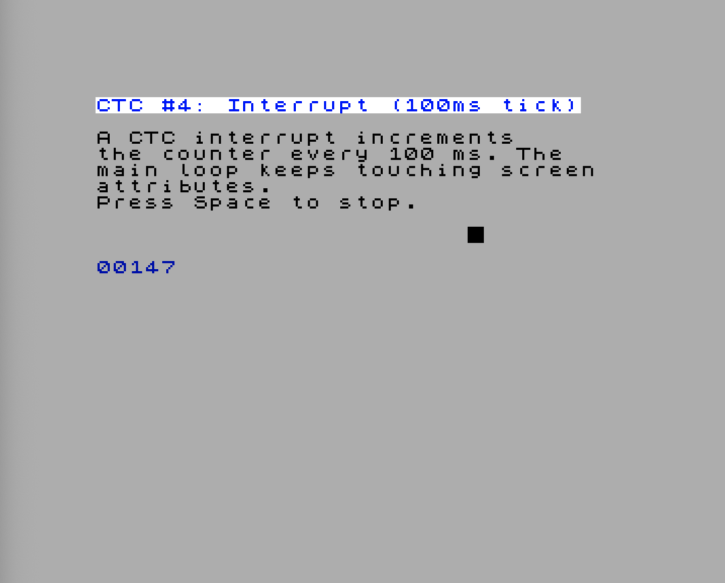
On real hardware, treat that as the starting point rather than a calibrated stopwatch. The CTC runs from the active system clock domain, and its exact wall-clock rate depends on the active timing configuration and the CTC’s divider behavior. If a 60-second stopwatch run produces 545 ticks instead of 600, the ISR logic is not losing ticks; the real divider chain is simply not matching the clean nominal calculation. For wall-clock-accurate ticks, measure the active rate on your target mode and adjust the three time constants accordingly.
Combining CTC Interrupts with DMA
The Next can trigger DMA transfers directly from CTC ZC/TO events — no CPU involvement required. NextReg $CD controls which CTC channels can wake the DMA:
- Bits [3:0]: CTC channels 0–3 enable DMA trigger (bit 0 = channel 0)
This is powerful for audio streaming: set a CTC channel to fire at your sample rate, connect it to DMA, and the DMA automatically transfers the next sample to the DAC on every CTC tick. The CPU never touches the audio path.
    ; Enable CTC Channel 0 as DMA trigger
    ld a,$CD
    ld bc,NR_REG
    out (c),a
    ld a,%00000001          ; Channel 0 triggers DMA
    ld bc,NR_DAT
    out (c),a
The DMA must be configured separately with the transfer parameters — the CTC just provides the trigger signal. The zxnDMA chapter covers the full CTC-triggered DMA pattern, and the DAC and Sample Playback chapter shows how it’s used for audio.
ZC/TO Chaining in Detail
The four channels form a circular chain of ZC/TO connections:
    Ch0 ←── ZC/TO ── Ch3
     │                 ↑
     ZC/TO             ZC/TO
     ↓                 │
    Ch1 ──── ZC/TO ──→ Ch2
Each channel’s ZC/TO output feeds the next channel’s external trigger input:
- Channel 3 → Channel 0
- Channel 0 → Channel 1
- Channel 1 → Channel 2
- Channel 2 → Channel 3
This creates interesting possibilities:
- 16-bit timer: Channel 0 in timer mode with Channel 1 in counter mode (as shown in the cascaded timing example)
- 24-bit timer: Chain three channels (timer → counter → counter)
- Frequency divider: Each channel divides its input by its time constant
- Complex periodic signals: Chain channels with different time constants to generate intricate timing patterns
One thing to keep in mind: the ZC/TO pulse lasts exactly one system clock cycle (35.7 ns). The downstream channel in counter mode sees this as a single decrement event.
Joystick clock: Channel 3’s ZC/TO output, divided by 2, also drives the joystick serial clock when configured for I/O mode. If you’re using Channel 3 for timing, check that you haven’t accidentally changed your joystick behavior.
Soft Reset: Recovering from Unknown State
If you’re writing initialization code that might need to deal with CTC channels left in an unpredictable state by previous software (e.g., a game returning to BASIC, or a dot command), the safe reset procedure is:
    ; Safely reset Channel 0 regardless of current state
    ld bc,$183B
    ld a,%00000011          ; D1=1 (soft reset), D0=1 (control word), D2=0
    out (c),a               ; First write: might be eaten as time constant
    out (c),a               ; Second write: guaranteed to be read as control word
    ; Channel is now in CONTROL_WORD state, ready for fresh configuration
Why twice? If the channel was in the TIME_CONSTANT state (waiting for a time constant byte), the first write is consumed as a time constant, not as a control word — even if D0=1. The second write hits the channel when it’s definitely expecting a control word. Writing twice with D2=0 (no time constant follows) guarantees the channel ends up in the CONTROL_WORD state.
Gotchas and Tips
The CTC isn’t affected by CPU speed. We’ve said it before, but it bears repeating. NextReg $07 changes the CPU clock, not the system clock. The CTC always runs at 28 MHz. This means CTC-based timing measures real time, not instruction time.
Reading the counter is a snapshot. The counter continues running between the IN instruction and the time your code uses the value. For best accuracy, keep the code between the two IN reads as short as possible.
Time constant 0 = 256. This is standard Zilog behavior. Loading 0 gives you the maximum count range (256 ticks before ZC/TO). Loading 1 gives the minimum (1 tick before ZC/TO, i.e., ZC/TO fires on the very next prescaler pulse).
The time constant reloads automatically. Once a channel is running, reaching zero does not stop it. The CTC emits ZC/TO, reloads the counter from the stored time constant, and carries on. This is why periodic interrupt handlers usually clear the interrupt status and return; they do not rewrite the CTC time constant on every tick.
Prescaler phase matters. The prescaler is a free-running 8-bit counter that is never explicitly reset in normal operation. When your time constant loads after a control word write, the first tick might arrive slightly earlier or later than expected, depending on where the prescaler happens to be. For single-shot measurements, this adds up to ±1 tick of jitter. Over multiple ZC/TO periods, it averages out.
Don’t change D4 while running. Writing a control word that changes the trigger edge (D4) counts as a clock edge internally. If the channel is running, this can cause an unexpected decrement. Configure D4 before starting the channel.
Interrupt status must be cleared manually. After servicing a CTC interrupt, write a 1 to the corresponding bit in NextReg $C9 to clear the status. If you forget, the interrupt will not fire again (the status bit stays set and blocks new triggers).
Where Next
- The zxnDMA: Moving Data Without the CPU uses the CTC as an external pacing source, which is especially handy for audio-style transfers where “roughly now” is not good enough.
- Interrupts explains the IM2 machinery behind CTC interrupt handlers, vector tables, and the Next’s hardware interrupt controller.
- I/O Ports and NextRegs is worth keeping nearby whenever you configure CTC-related NextRegs or port-based peripherals.